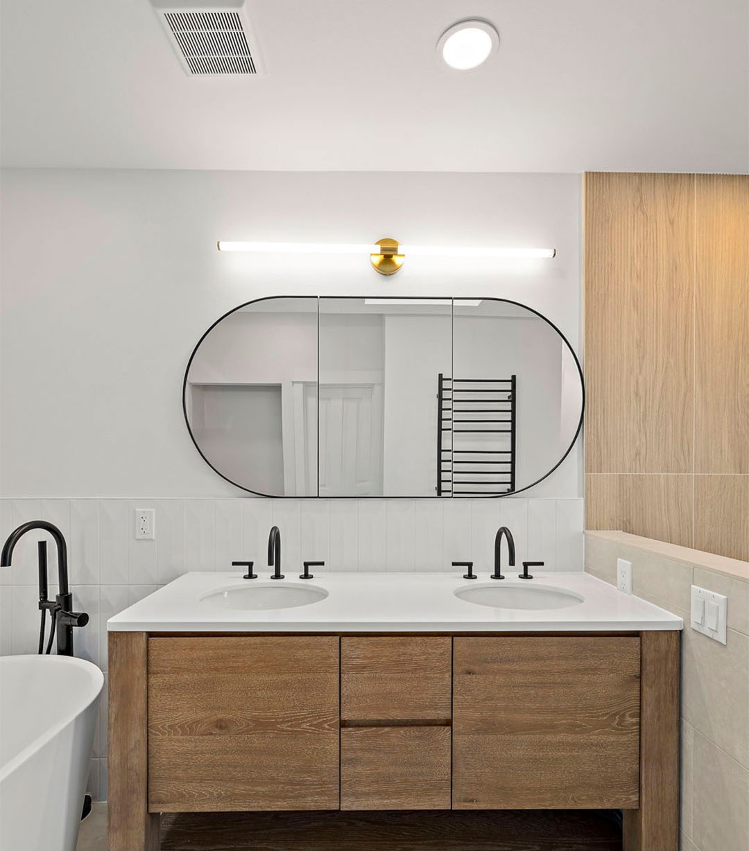




















Linear LED is the most efficient lighting most new buildings will get. It is also a long, narrow cut in the ceiling, and in a growing share of high-performance buildings the ceiling board is the air barrier.
By LEDSON, a European manufacturer of aluminum LED profiles.
Energy raters have spent years teaching builders to distrust recessed cans. Linear lighting has mostly escaped that scrutiny, because it reads as a finish detail rather than a fixture. On the drawings it is a line. In the ceiling assembly it is a slot that can run 12 or 20 feet (about 4 to 6 meters) with an aluminum extrusion sitting in it. Where the board it cuts through is also the air barrier, that slot deserves at least the attention a single can gets, and more once a blower-door test is part of sign-off.
Where the problem actually occurs
In most commercial buildings the suspended ceiling is already a service zone. The air barrier sits at the roof deck or the top-floor slab, and light lines live below it without touching it. The problem appears where the ceiling finish itself carries the barrier: houses and apartments under vented roof spaces, and timber-frame or modular schools, offices and care homes built to tight airtightness targets. Those are exactly the buildings where linear light has become the default for kitchens, corridors and open-plan rooms.
A channel is an open extrusion, not an airtight housing
For cans, the rules are explicit. The IECC requires a recessed luminaire installed in the building thermal envelope to be IC-rated, labeled for air leakage of no more than 2.0 cfm at a 75-pascal pressure difference, and sealed to the ceiling finish with a gasket or caulk. Passivhaus projects and new homes in the UK face the same logic through mandatory airtightness testing.
An aluminum LED channel meets none of that, and it was never meant to. It is an open extrusion closed by a snap-in diffuser and two end caps, which makes it a very good heat sink and a poor air seal. Recess one into an air-barrier ceiling under a vented roof space and the whole run becomes a leakage path, joints and end caps included. In a heating climate that air carries indoor moisture into the roof space, where it can condense on cold framing and sheathing long before anyone notices.
Three places a recessed run can go without cutting the barrier
The simplest fix is location. A ceiling between two conditioned floors is not part of the envelope, so a recessed run there costs nothing in airtightness. The lower floors of a multi-story building are the natural home for recessed linear light.
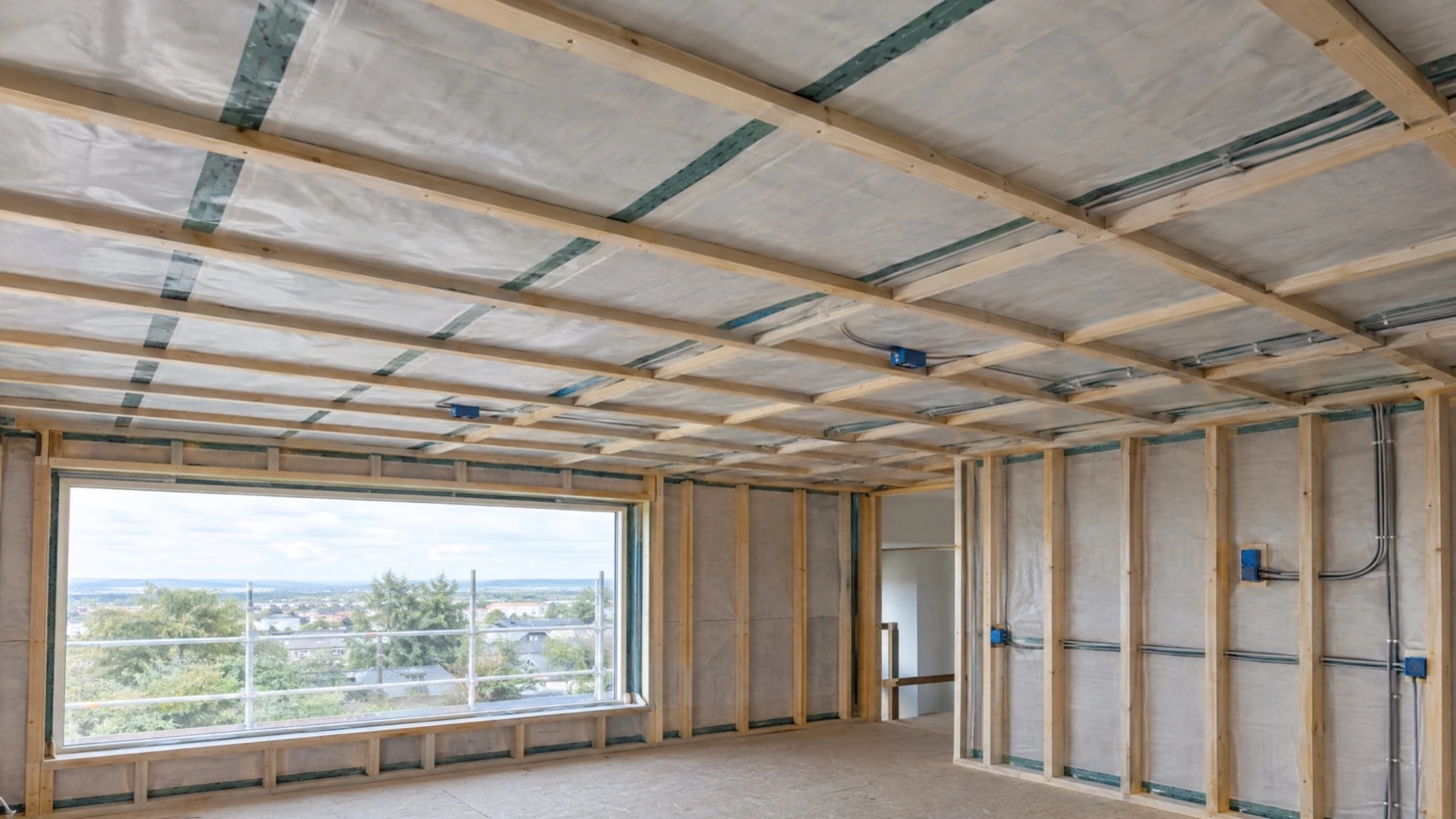
On a top floor, build a service cavity. Fur the ceiling down below the air barrier (2x3s on edge in timber work, a light steel grid in commercial fit-outs) and hang the board on the furring. The channel, its wiring and its junction boxes live in that cavity, and the barrier above stays uncut. Size the cavity for the driver rather than the strip: the driver is usually the bulkiest part of the system, and it has to stay reachable.
The third option is a dropped soffit or cove built inside the envelope. A cove throws light up onto the ceiling from below, so the source never sits in the barrier plane at all, and in a corridor or meeting room the effect is often better than a recessed line anyway.
If none of that is possible, as in a retrofit where the top-floor ceiling has to stay where it is, mount a surface or suspended profile instead of recessing one. The line still reads as architecture, and the board above it stays whole.
Insulation around the channel changes its rating
The extrusion is the only path pulling heat away from the diodes, so it has to shed that heat into air. Published thermal ratings assume 25 °C (77 °F) around the profile. Across one European manufacturer’s range, a 6 x 14 mm micro profile carrying up to 10 W per meter (about 3 W per foot) settles near 42 °C (108 °F) at that ambient, and a 116 mm wide architectural body carrying up to 55 W per meter (about 17 W per foot) settles near 58 °C (136 °F).
Pack insulation against that body, or close it into an unvented box, and the air around it is no longer 25 °C. Diode life tracks junction temperature: every 10 °C (18 °F) above the rated point roughly halves the expected life. A strip labeled for tens of thousands of hours can lose most of them in a cavity nobody measured.
A workable sizing rule takes three steps. Use the strip’s real wattage rather than the maximum printed on the label. Measure the temperature of the space where the channel will sit and add 5 °C (9 °F). Then choose a profile rated above that load at that temperature. A channel in a service cavity sits in conditioned air, close to the conditions its rating assumes, so the cavity that protects the air barrier protects the LEDs as well.
Plan the service path before the board goes up
Drivers and strips get replaced; extrusions buried in a finished ceiling usually do not. Some trimless systems are installed in two stages: the body is set and finished with the ceiling, and the LED insert goes in afterwards, held by neodymium magnets with a safety cable. The strip can then come out from below without touching the plaster or the barrier above it. Whatever the system, keep drivers in the service cavity behind an access panel, or in an adjacent closet or riser, never sealed above an airtight ceiling.
Bathrooms, kitchens and exterior soffits add moisture to the list. Match protection to the zone: IP20 for dry interiors, IP44 where splashing is possible, IP67 for wet, exterior or immersion locations. North American inspectors will also look for the damp- or wet-location listing on the complete fixture, so check both.
The most efficient light in the building should not be its leakiest detail. Keep recessed runs out of the air-barrier plane, give the extrusion air at the temperature its rating assumes, and size it on paper before the ceiling closes. Manufacturers that publish watts per meter at a stated ambient, Ledson among them, give you the numbers to do that math.