


Designing a house in the United States requires a balance between creative freedom and compliance with building regulations. The International Residential Code (IRC) and other state-specific rules define the framework for what must appear in a construction plan — but within those boundaries, architects and homeowners have wide freedom in how they design. Plan7Architect is a CAD program that brings this flexibility into a straightforward environment, making it possible to create complete residential drawings in 2D and 3D while using American measurement units and conventions.
Floor Plans and Dimensions
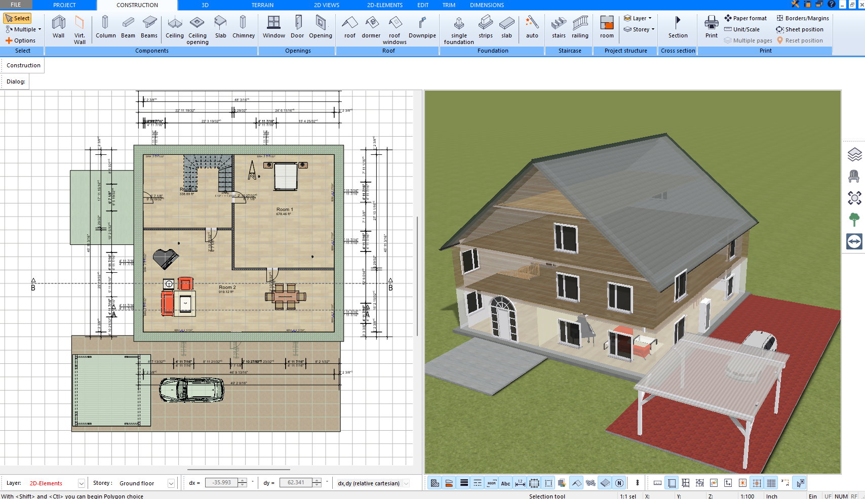
Plan7Architect works natively in feet and inches, allowing plans to be drawn precisely in the scale and units used throughout the U.S. construction industry. Rooms can be labeled automatically, with their names, floor areas, and ceiling heights shown directly on the plan.
The dimensioning system follows American drafting practice — aligned, baseline, or continuous dimensions are supported, and all text and annotation styles can be customised. Because each line and reference point can be adjusted freely, the program adapts to almost any office or permit-drawing standard without limitation.
Space calculations can distinguish between finished and unfinished areas and produce total floor-area summaries consistent with the measurement methods typically used in U.S. real estate and design documentation.
Wall Construction, Doors, and Windows
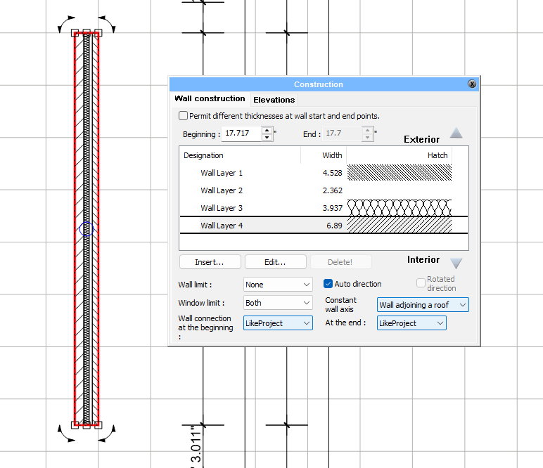
One of the strengths of Plan7Architect is its open construction logic. Wall assemblies, doors, and windows are not restricted to fixed templates — they can be defined, edited, and saved entirely by the user.
Wall structures may include any number of layers with freely assigned thicknesses and materials, from conventional 2×4 or 2×6 wood framing to steel studs, concrete block, or insulated panel systems. Each layer can be named, reordered, and given its own surface appearance in both 2D and 3D.
Doors and windows can likewise be selected from an extensive library or created from scratch. Sizes, frame depths, sash divisions, glass types, and trim details are all editable. Openings automatically adapt to wall thickness, and custom assemblies can be reused across projects.
This level of flexibility means that even non-standard details — arched windows, oversized sliding doors, or specialty glazing — can be modeled exactly as they would be built.
Roof Design
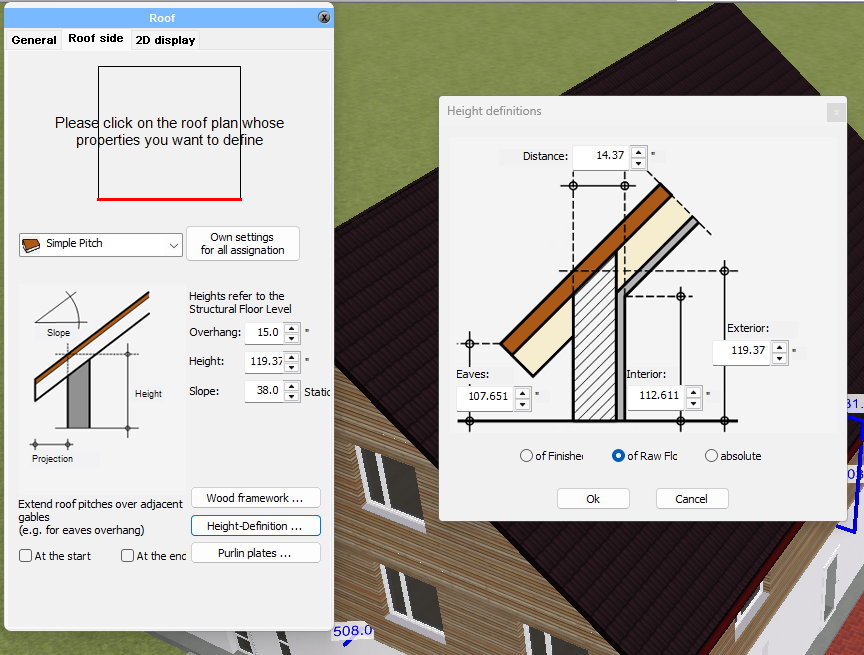
Roof design in Plan7Architect is entirely parametric and unrestricted. Users can begin with any geometry — gable, hip, flat, shed, gambrel, butterfly, or complex multi-roof combinations — and modify every angle, intersection, and layer.
Pitches can be entered as degrees, ratios (for example 6/12), or numeric rise and run values. Every roof plane can be connected, cut, or extended individually, making irregular or custom architectural forms just as straightforward as standard ones.
Openings such as dormers, skylights, chimneys, or ventilation shafts can be placed anywhere and adjusted freely in size and shape. Because the roof model is fully editable, Plan7Architect can reproduce virtually any roof configuration encountered in residential or small-scale architectural work.
Stairs and Levels
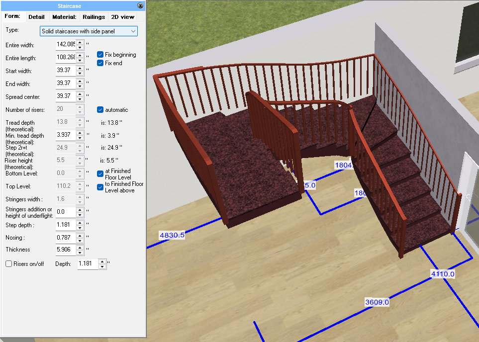
The stair system is equally flexible. Users can start from straight, L-shaped, U-shaped, curved, or spiral layouts and adjust each geometric parameter independently — rise, run, tread width, railing height, landing dimensions, and headroom. The resulting geometry can reflect exact IRC guidelines for residential stairs or any local variant.
Projects with multiple stories are managed through the program’s story structure, where each level’s height, reference elevation, and alignment can be customised. Floor-to-floor and ceiling heights are entered in feet and inches, ensuring consistent relationships between plans, sections, and elevations across all levels.
Elevations, Sections, and Documentation
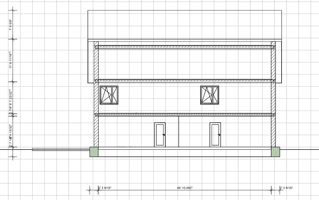
From a single 3D model, Plan7Architect generates elevations and cross-sections automatically. These drawings display structural heights, window and door openings, roof lines, and material hatchings clearly and precisely.
Annotation tools, text styles, and line weights can be defined according to any office standard. Layers follow a structure compatible with AIA-style naming, and sheets can include custom title blocks with project data, notes, and scale bars.
Plans can be exported as DWG, DXF, or PDF, using standard U.S. paper sizes such as 24×36 in (ARCH D) and 11×17 in (ARCH B). The exported drawings are scale-accurate and ready for coordination or submittal.
Foundations and Framing
Plan7Architect supports all common foundation types used in American residential construction — slab-on-grade, crawlspace, basement, pier-and-beam, or custom hybrid systems. Each can be edited and extended freely: footing widths, wall depths, stem walls, and slab thickness are fully adjustable.
The structural representation is not limited to predefined assemblies. Users can design any framing logic they need — from typical 16″-on-center wood studs to engineered lumber or light-gauge steel. Floor joists, beams, and roof trusses can be displayed, labeled, and coordinated directly in the plan or section view.
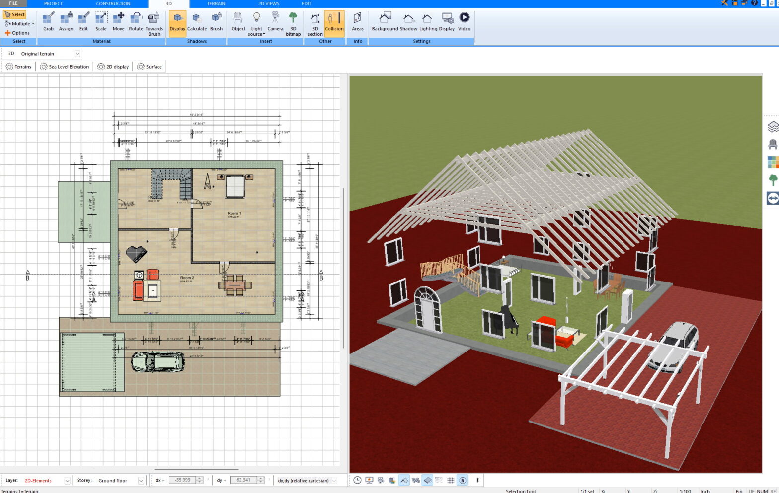
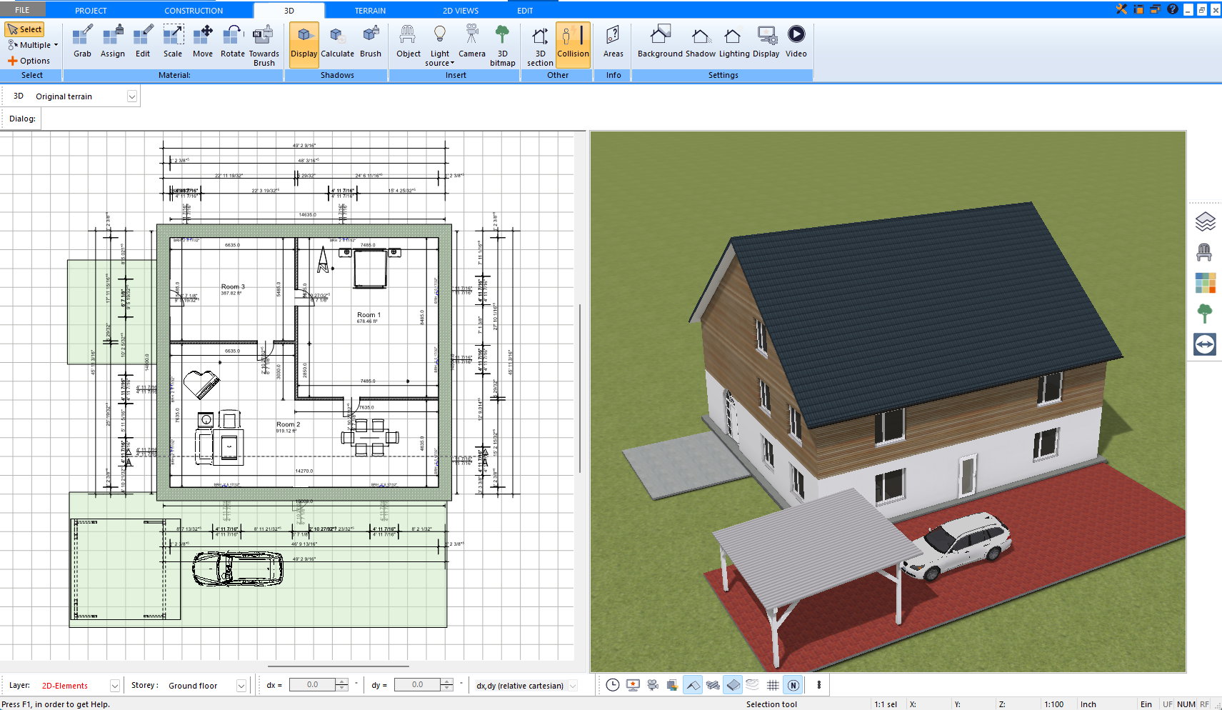
Visualisation and 3D Presentation
The program links every 2D plan element with a 3D model. With one click, users can switch between technical drafting and realistic visualisation. Materials can be assigned to any surface: asphalt shingles, metal roofing, wood siding, drywall, or custom textures.
Lighting, shadows, and sun positions can be simulated according to the project’s geographic location within the United States. Walkthrough and camera tools allow detailed visual review, making it easier to evaluate proportions and interior layouts before construction begins.
Collaboration and Output
Plan7Architect supports a wide range of file formats to ensure smooth collaboration with other design and visualisation tools. Drawings can be exported as DWG or DXF, preserving layers, line weights, and annotations for direct exchange with architects, engineers, or contractors using AutoCAD or similar software. PDF export allows scaled plan sets to be printed or shared digitally in standard U.S. paper sizes.
For visualization and rendering workflows, the program includes 3DS and OBJ export, enabling direct transfer of 3D models into platforms such as Twinmotion, Lumion, Enscape, or Blender. Surfaces, materials, and textures are maintained, allowing realistic scene composition without additional conversion steps.
Users can also import and edit SketchUp models, giving access to the vast online libraries of 3D objects and components widely used in American design practice. This makes it easy to integrate furniture, fixtures, and landscape elements into architectural scenes.
For technical applications, the software supports STL export for 3D printing — ideal for creating physical scale models directly from the digital design.
Together, these options create an open workflow: plans, models, and renderings can move freely between Plan7Architect and the broader ecosystem of design, visualisation, and fabrication tools.
Everyday Use and Applications
The software’s workflow suits a wide range of users: private homeowners who want to plan and visualise their projects in detail, builders who prepare plan sets for permitting, and small design firms that need a flexible, reliable CAD environment. Because every aspect of the model can be defined individually, the program adapts to both standard and highly specific architectural solutions without compromise.
Conclusion
Plan7Architect Pro offers a broad, adaptable platform for residential design in the United States. It combines U.S. measurement units, drawing conventions, and code-aware geometry with a high degree of freedom: walls, roofs, foundations, stairs, and openings can all be configured in unlimited variations.
For those who want a single tool to draw, model, and document homes in a way that aligns with American building practice, Plan7Architect provides a capable and precise solution — as flexible as the architecture itself.